One of the best parts of my job is getting out into the field. I am always amazed at the ingenuity and ways people solve their work truck application issues. Work trucks are designed to do just that: work. They must be in usable condition to make the company money. Our goal is to maximize uptime and productivity and minimize downtime and maintenance costs.
The Power Take-Off (PTO) needs the correct torque rating, right bolt hole pattern, exact mating gear, and proper ratio. A truck needs all that coupled with the appropriately balanced driveline and vacuum pump combination to work correctly.
The following is a story from a troubleshooting trip from the field on a Class 8 truck used to pump water:
TROUBLE IN THE WEST
Business is booming these days, and time is money. The Southwest is heating up, and the dusty, dry dirt is swirling. I got a call about a PTO that wasn’t working, and the conversation began.
First things first: “What is the application?” The company has about 10 Class 8 trucks, all used to haul water in the oil field. They run two 12-hour shifts, seven days a week. The trucks are new and have been in service about a year. They idle at 1,100 RPMs and have a 30-inch driveline attached to a PTO connected to a 90-degree gearbox that is coupled to a vacuum pump via a flexible coupling. Does this sound familiar?
I get in a car to see it for myself.
I arrive at the yard to meet the service manager. I ask him and the mechanic to tell me what happened. “The truck was working fine, then all of a sudden it locked up and would not pump,” the manager says. That seems simple enough, but I have a few more questions to ask while there.
WHAT WE’VE GOT
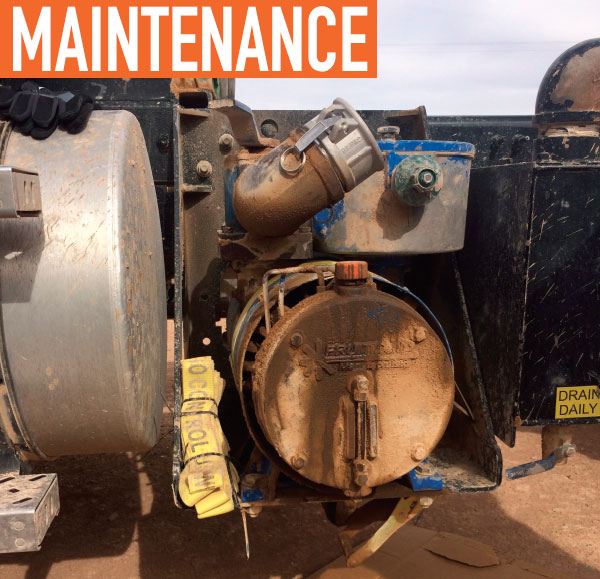
As an engineer, I am very curious, and there are some telltale signs it isn’t as simple as the PTO “just locked up.” I inspect the driveline setup on the truck. I ask why the vacuum pump isn’t bolted down to its mounting bracket. I also notice it is held on with a 2-inch-wide tie-down strap. (See image 1.) The mechanic jumps in and says the pump feet broke, and they had to do something to keep the truck working in the field.
Secondly, I ask the manager if the gearbox shaft and vacuum pump shaft look like they are concentric and parallel. (See image 2.) “No they don’t, but that is how they delivered them to us,” he says. He goes on to tell me that they go through two or three flexible couplings a week. He says the smaller couplings don’t hold up. He is having bigger ones machined in hopes they will last longer.
Finally, I ask if he knows the driveshaft angle from the PTO to the gearbox. He doesn’t know it, but he does say it looks a little steep. I thought the same thing. (See image 3.)
SETUP MEASUREMENT
I start to get to work. I note some observations: the driveshaft is tubular, there is a slip yoke, the shaft yokes are in phase, and the u-joints are freshly greased. Perfect! The next step is to take a few measurements with a simple tape measure. The driveline measures 30.5 inches center-to-center. Easy! The hard part is accurately measuring the offset of the PTO centerline to the gearbox centerline. Remember, I’m using a tape measure. After looking at it several ways and taking multiple measurements, the average looked to be 5 inches. Now it’s just simple math. The angle calculation is a simple trig function: SinΘ = Opposite/Hypotenuse. The opposite leg is 5 inches. The hypotenuse is 30.5 inches. 5/30.5 = 0.16. Therefore, the theoretical angle is approximately 9.4 degrees.
I go back to the manager to discuss what I found. Once I show him the 9.4-degree angle he says, “I thought it looked too steep.” He tells me when he used to set up drivelines three to four degrees was the max. You can go to higher angles, but the driveline speed needs to the reduced appropriately. He now realizes the angle needs to be reduced some and/or slow the shaft RPM down. He also shares with me the fact the bolts get loose and need to be tightened periodically. That indicates there is a lot of unintentional vibration somewhere.
Next, I focus on the 90-degree gearbox and pump coupling. I measure both sides of the coupling. They should be almost the same, however, there is nearly a 1/8-inch difference. I show this to the manager, and he recognizes that it isn’t right. He also realizes the new flexible coupling won’t last for long. Again, he said the truck had a lot of vibration. It was new and he thought the vibration was too much.
SOLUTION: SETUP
After a lot of head scratching and what if’n, we both agree the setup needs to be addressed. Like most companies, they are shorthanded, with few drivers working long hours and little downtime to schedule adequate repairs. I tell him my goal is to improve his uptime and productivity and minimize future maintenance cost. The PTO is not the problem. It’s the setup that is the issue.
This is not a quick and easy fix. There are a few areas to address. The driveline angle and RPMs from the PTO to the gear box should be reduced. There is information on the internet to help you setup drive angles based on shaft speed. It is very important to know the required input speed for the vacuum pump. You don’t want to over speed it, and if you can run the driveshaft slower, the driveline angle can be more forgiving. More importantly, before the driveline speed and angle are addressed, the gearbox and vacuum pump shaft’s concentricity must be tackled. Flexible couplings should last a long, long time. The pump and gearbox shaft must be relatively concentric and parallel. The damage to the pump, and the fact it is tied down, indicates there are some contributing factors—the install, application, speed, environment, and/or alignment. It is unclear how and when this could have occurred. Moving the vacuum pump is challenging due to hoses, fittings, and limited space. Truck space is at a premium these days, and the available space is shrinking all the time.
WRAP UP
As I leave, the yard the manager and I shake hands, and we thank each other for our time and input troubleshooting the truck. Sometimes it takes a new set of eyes to show you what you’re overlooking, or possibly even neglecting. I look forward to seeing the new setup, which will improve uptime, productivity, and reduce maintenance costs. And, I am sure the service manager will be glad to have the trucks up and running relatively trouble-free as they continue to build our world.
ABOUT THE AUTHOR
Mikel Janitz is a territory manager of OEM applications engineering with Bezares USA. Find out more, visit www.bezares.com or www.pto.usa.com.
MODERN WORKTRUCK SOLUTIONS: MAY 2018 ISSUE
Did you enjoy this article?
Subscribe to the FREE Digital Edition of Modern WorkTruck Solutions magazine.
![]()


